Xiaomi Mi Band 4
Board |
|
Vendor |
xiaomi |
SoC |
da14697 |
Overview
The Xiaomi Mi Band 4 is a fitness tracker built around the Renesas SmartBond DA14697 SoC, an ARM Cortex-M33 with an integrated Bluetooth LE 5.0 radio. This board definition is the result of reverse engineering the device so it can run open-source Zephyr RTOS based firmware.
Hardware
Renesas SmartBond DA14697 SoC
ARM Cortex-M33 core
512 KiB SRAM
Bluetooth LE 5.0
1.4 V - 3.6 V supply
16 MiB external QSPI flash, mapped at
0x1600000032 MHz and 32.768 kHz external crystals
Raydium RM69310 AMOLED display driver (120 x 240, RGB565)
Zinitix touch controller (I2C)
Bosch BMI260 6-axis IMU (I2C)
Texas Instruments AFE4900 heart rate analog front end (SPI/I2C)
Azoteq IQS620 proximity / wear detection sensor (I2C)
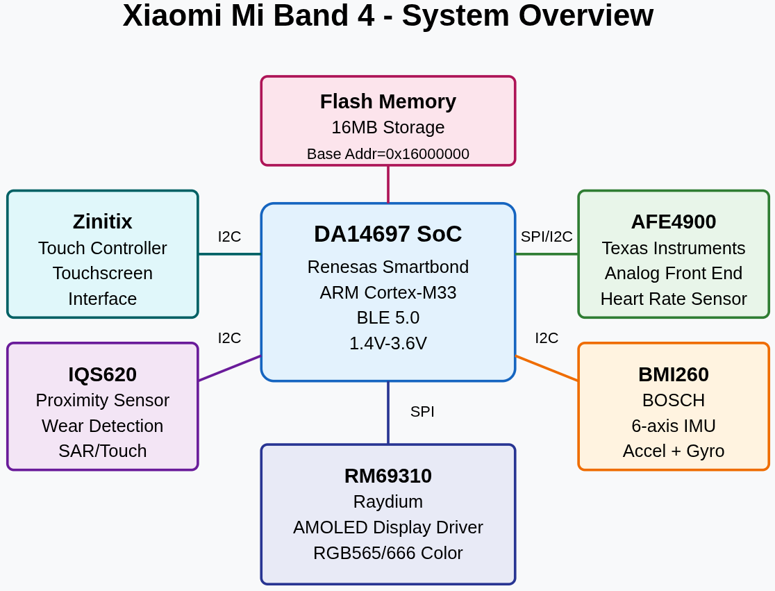
System overview
Datasheets for the main components are available in the doc/datasheets directory of this repository.
Supported Features
The following features are supported (from the board’s twister YAML file):
Feature |
Target |
|---|---|
counter |
mi_band_4 |
gpio |
mi_band_4 |
hwinfo |
mi_band_4 |
watchdog |
mi_band_4 |
i2c |
mi_band_4 |
rtc |
mi_band_4 |
crypto |
mi_band_4 |
dma |
mi_band_4 |
memc |
mi_band_4 |
The following components are not supported yet:
Touch controller
IMU
Heart rate sensor
Proximity sensor
Power management and battery charging
Connections and IOs
Debug Pads
The SWD interface and power are exposed on test pads on the back of the PCB.
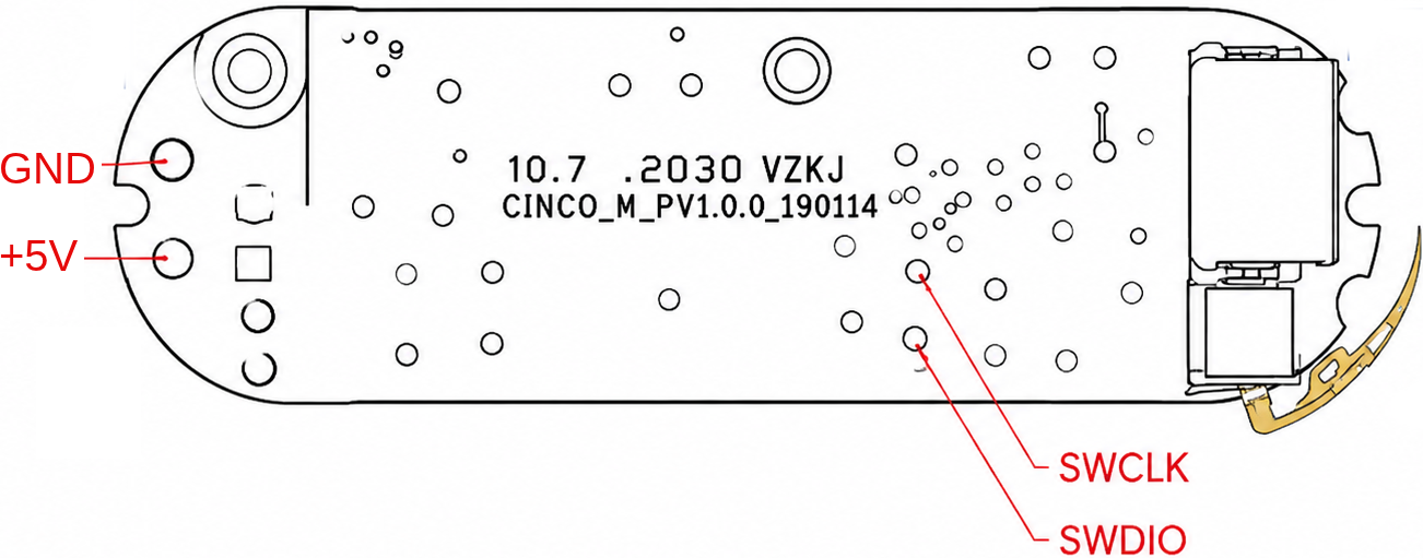
SWD and power test pads
Pad |
Connect to |
|---|---|
GND |
Debug probe GND |
+5V |
5 V supply |
SWCLK |
Debug probe SWCLK |
SWDIO |
Debug probe SWDIO |
Programming and Debugging
The following west runners are supported:
Runner |
Default |
|---|---|
ezflashcli |
yes |
jlink |
Set up the Workspace
This repository is a west manifest repository and a Zephyr module, so the
mi_band_4 board is available to west build once the workspace is
initialized:
west init -m https://github.com/walidbadar/ZSband --mr main zsband-workspace
cd zsband-workspace
west update
west zephyr-export
west packages pip --install
Building
Here is an example for the Hello World application:
west build -b mi_band_4 zephyr/samples/hello_world
The board defconfig disables XIP (CONFIG_XIP=n) so that images can be
loaded directly into SRAM for debugging. To build an image that executes from
flash, enable XIP:
west build -b mi_band_4 zephyr/samples/hello_world -- -DCONFIG_XIP=y
Flashing
The board supports the ezflashcli (default) and jlink runners. After
building an XIP image, flash it with:
west flash
To use J-Link instead:
west flash -r jlink
Loading into RAM
A non-XIP image can be loaded into SRAM and started without touching the flash
using the J-Link helper script. It reads the initial stack pointer and reset
vector from the image, loads zephyr.bin at 0x20000000 and jumps to it:
ZEPHYR_BASE=$PWD ZSband/scripts/jlink/ram-load.sh [MCU] [SRAM_BASE_ADDR]
MCU defaults to DA14697 and SRAM_BASE_ADDR to 0x20000000. The
script expects the build directory at $ZEPHYR_BASE/build.
Debugging
Debug the application with J-Link:
west debug -r jlink
The console is routed to SEGGER RTT by default (CONFIG_RTT_CONSOLE=y). Open
it with JLinkRTTViewer or JLinkRTTClient while the target is connected.
The UART is also available on P0.8/P0.9 at 115200 baud.
Connecting to the Target
The SWD pads can be hard to keep in contact with. The auto-connect scripts retry until the target is detected, which helps with positioning the probe pins:
# J-Link, beeps when the target is found
cd ZSband/scripts/jlink && ./auto-connect.py

# Raspberry Pi SWD adapter (SWDIO = GPIO 23, SWCLK = GPIO 24)
cd ZSband/scripts/openocd && ./auto-connect.sh
Reading the Stock Firmware
The whole 16 MiB flash can be dumped with OpenOCD through a Raspberry Pi SWD
adapter. The image is written to output.bin:
cd ZSband/scripts/openocd && ./flash-reader.sh